aight ya’ll, I finally got around to finishing my power locks and I am so happy I finally did it! And suprisingly, after I figured out the correct way to wire them (went to a custom car shop and they told me lol) it’s really not hard! The hardest part is just getting the alarm system installed to use em (I don’t say how to do that here….), but you could also get the door-lock switches (I’ll be getting some soon, just gotta go to a junk yard and buy some – any 3 wire switches’ll do — i explain how one WOULD install em).
first off, here’s whatcha need:
http://cgi.ebay.com/ws/eBayISAPI.dll?ViewItem&item=150045275499
1) this is the door — we start by taking off the door panel. the red circles are where screws are: 4 on the bottom, 2 under the arm rest thing, and 1 in handle — then there’s the knob for the window (green circle) — (yellow arrow is for later):
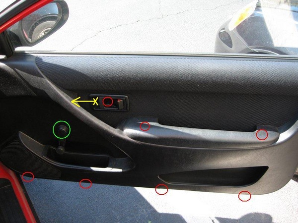
2) here are some pictures of where the screws are and stuff from step 1:
to remove the window crank knob, i usually use a very small flat head screw drive to pry the horse shoe lock off/out (check out terseoman’s post over at torontopaseoclub.com on speaker install to see what it looks like:
http://www.torontopaseoclub.com/modules.php?name=Forums&file=viewtopic&t=806
3) now, to actually remove the panel, start off by sliding the door handle towards the hinge of the door (refer to yellow arrow in step (1). The handle should now be loose, and able to be pulled away from the door a LITTLE bit (don’t pull it out alot, it can bend the metal bars).
With all the screws removed, and the crank knob, you can pull off the lower 3/4 of the panel by just tugging on it (there’s those plastic “push pins” along the edges of the panel which hold the panel to the door) — then w/the bottom pulled away from the door, use your palm and hit the bottom of the panel (where the 4 screws came out) so it comes loose on the top. While turning the panel around the hinge (see pic below) and not letting the handle move too far away from the door and not letting it (handle) twist too much, remove the panel! (again, don’t let the metal bars going to the handle bend — dunno if it’d mess things up)
4) now, remove the 2 bolts (red) and take off the bar thing, and cut away the plasic (green) — I later tape the plastic back the way it was, just cause it’s gotta be there for a reason, right? (keep dirt n’stuff away from window? i dunno…) — and if you’re wondering why i have the middle section replaced it’s cause my car was busted into and i had to replace the window :(
5) finally, the power lock! okay, so first take the “L” bar and feed it through the tip of the actuator so the bar comes out the “top” of the actuator (don’t know how to explain that better….just look at the picture haha) then go ahead and use two of the screws and place them in the 3rd and 5th slot on the mounting bar. Don’t tighten the screws all the way yet, but get em tight enough to not let the actuator easily slide left and right on the mounting bar
then, put in the metal thing that acts as a nut for mounting the right ride of the mounting bar (you should be able to put it on the “first” hole like i did)
6) slide the metal thing down the L bar which screws on and attaches to the “locking bar” (tighten the screws on it just so it loosely holds onto the locking bar) — feed the “L bar” behind the plastic, in between the bar that is the lock and the bar that is the handle (lock and unlock the door if you are confused which one, u want to attach the L Bar to the one that moves when you lock/unlock the door). and place the left end of the mounting bar where one of the previous bolts was and the right end inside the door (see pic) go ahead and screw in the bolt (red) w/the bar there so we can determine where to drill the hole (green) for the right side and where to position the actuator.
7) unlock the door, and fully extend the actuator. now, slide the actuator right (or left) so that it’s in a good place (not running into the frame (red) ), and try to make it so the L bar is a parallel w/the locking bar as possible.
with everything in place as you want it, tighten the screws on the metal “attacher” on the L bar — tighten it pretty good (not sure if those screws are plastic? so be careful not to over tighten)
8 ) roll down the window to make sure that the actuator isn’t in the way (I dont think you could even if you tried, but just to be safe!). If all is good, either remove the actuator setup if you want, or simply push the actuator in a towards the door a bit so you don’t drill into it :) — get your drill and make your hole for the right side of the mounting bar to be secured. (it doesn’t have to be EXACT since you have like an inch wide hole on the mounting bar) — be careful not to drill into the wires of the actuator either!
9) test it. put the screw back that holds the handle in place (so ti won’t move around when unlocking/locking) — get a good ground and a +12v source — attach one wire to ground, and the other to +12v, it should either lock or unlock, then swap the wires and it should do the oppesite! (if it’s not working, check your ground (or get a new actuator? lol :( ) – NOTE: don’t keep it connected for a long time, i dont’ know if having it keep on trying to lock’unlock for a long time would break it!
if all is working, remove the bolt holding the left side of mounting bar, run the wires down around the plastic (make sure there’s no “slack” left behind the plastic to get caught by the window) and run it towards the speaker.
10) now to route the wiring — remove the speaker (there’s 3 bolt/screws holding it on) — to get the wire to follow the rubber tube that the speaker wire goes through, i got a thick guage wire (spose you could use a hanger or something similar), fed it through the tube (i had to keep twisting the wire and massaging the tube to work it through — this took a while…) and w/it though, i wrapped the actuator wire around one end, taped it up, and pulled it though!
11) mount the relays — so i decided to mount the relays up under the dash, inside the top-left area (pic)
so the relay kit has 8 wires, 5 THICK (brown, which, purple, green, blue) and 3 THIN (red, blue, green): (not that a pic would really help here….but here’s one anyway)
THICK blue and green: attach these to the blue and green wires from the actuator(s)
The THICK brown and white both go to ground (i’d recommend drilling a hole somewhere and use a screw to make a fresh ground – don’t forget to clear away any paint there too)
The THICK purple and the THIN red wire to go +12v source (again, I just attached this to my power wire to my neons and such — dunno if you’d want to piggy back on some random +12v wire…dunno how much current these things pull)
Now…… here’s the last step to get these to work…… you now need either a alarm system (i kno the Code Alarm, which I have, and the VIPER alarms have a 3-wire port coming from them, to which you would just match up the THIN blue and green wire the THIN blule and green wire from the alarm box (and don’t use/cut off the 3rd thin, red, coming from the alarm) — OR you can go to the junk yard (or does any paseo has power locks?) and get a power lock switch that has 3 wires coming from it, and you would attach the ground, THIN blule and green from relays, and you are SET!!!!
there you go! I think that’s everything….. let me know if i didn’t explain something clearly enough, and i’ll look over it
good luck! and feel free to ask any questions!!!!!